
Tel:13631651588
E-mail:lijie@szqyxkj.com
Address:Room 309, Building D, Weibaifu Building, Shekou, Nanshan District, Shenzhen
MOS tube common and uncommon knowledge
Source: Network Organization Posted in : 2021-11-08 14:41:23
About MOS tubes has always been one of the topics that engineers are keen to discuss, so we have sorted out the relevant knowledge of common and uncommon MOS tubes, hoping to help engineers. Let's talk about the very important component of the MOS tube!
anti-static protection
MOS tube is an insulated gate field effect transistor, the gate has no DC path, the input impedance is very high, it is easy to cause electrostatic charge accumulation, and a higher voltage is generated to drive the gate The insulating layer between the source and the source breaks down. Most of the MOS tubes produced in the early days did not have anti-static measures, so be very careful in storage and application, especially the MOS tubes with lower power. Since the input capacitance of the MOS tubes with lower power is relatively small, the voltage generated when exposed to static electricity Higher, it is easy to cause electrostatic breakdown.
The recent enhanced high-power MOS tubes are quite different. First of all, due to the large function and large input capacitance, there is a charging process when exposed to static electricity. , the voltage generated is small, the possibility of causing breakdown is small, and the current high-power MOS tube has a protective voltage regulator DZ (as shown in the figure below) on the internal gate and source, which embeds the static electricity in the Below the voltage-stabilizing value of the protection Zener diode, the insulating layer of the gate and the source is effectively protected. The voltage-stabilizing value of the protection Zener diode is different for different power and different types of MOS tubes. Although there are protective measures inside the MOS tube, we should also follow the anti-static operation rules when operating, which is what a qualified maintenance person should have.
Detection and substitution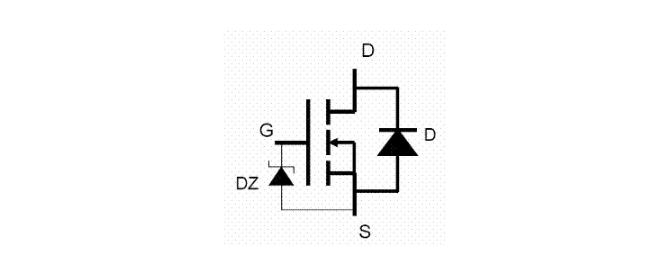
When repairing TVs and electrical equipment, various components will be damaged, including MOS tubes. This is how our maintenance personnel use common multimeters to judge the quality of MOS tubes. When replacing the MOS tube, if there is no same manufacturer and the same model, how to replace it.
1. MOS tube test:
As a general electrical TV repairer, when measuring transistors or diodes, they usually use ordinary multimeters to judge the quality of the transistors or diodes. Although the electrical parameters of the judged transistors or diodes cannot be confirmed, but as long as the method is correct There is no problem with confirming the "good" and "bad" transistors. Similarly, the MOS tube can also be judged by a multimeter to determine its "good" and "bad". From the perspective of general maintenance, it can also meet the needs.
The detection must use a pointer-type multimeter (digital meters are not suitable for measuring semiconductor devices). For the power MOSFET switches, they are all N-channel enhancement type, and the products of each manufacturer are almost all in the same TO-220F package form (referring to the field effect switch tube with a power of 50-200W in the switching power supply). The arrangement of the three electrodes is also the same, that is, the three pins are downward, the printing model is facing the self, the left pin is the gate, the right pin is the source, and the middle pin is the drain, as shown in the figure below.

1) Multimeter and related preparations:
First of all, you should use a multimeter before measurement, especially the application of ohm gear, to understand ohm The ohmic block will be correctly applied to measure the transistor and MOS tube.
The ohmic center scale of the ohm block of the multimeter should not be too large, less than 12Ω (12Ω for the 500 type meter), so that a large current can be obtained in the R×1 block. It is more accurate to judge the forward characteristics of the PN junction. The battery inside the R×10K block of the multimeter is greater than 9V, so it is more accurate to measure the reverse leakage current of the PN junction, otherwise the leakage will not be measured.
Now due to the progress of the production process, the screening and testing of the factory are very strict. We generally judge that the MOS tube has no leakage, no breakdown short circuit, no internal circuit, and can be enlarged. That's it, the method is extremely simple:
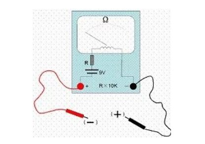
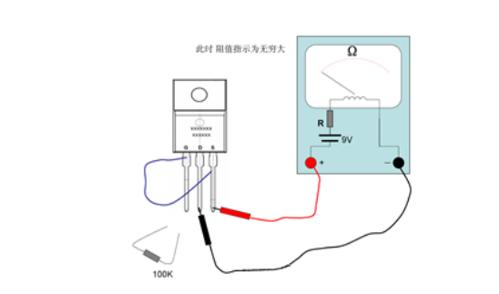
Using the R×10K block of the multimeter; the battery inside the R×10K block is generally 9V plus 1.5V to reach 10.5V. This voltage generally judges that the PN junction reverse phase leakage is enough , the red test lead of the multimeter is negative potential (connected to the negative electrode of the internal battery), and the black test lead of the multimeter is positive potential (connected to the positive electrode of the internal battery), as shown in the figure above.
2) Test steps:
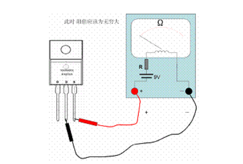
Connect the red test lead to the source S of the MOS tube; connect the black test lead to the drain D of the MOS tube. At this time, the needle indication should be infinite, as shown in the figure below. If there is an ohmic index, it means that the tube under test has leakage, and this tube cannot be used.
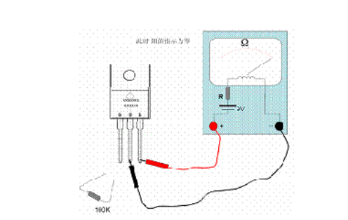
Keep the above state; at this time, connect a 100K~200K resistor to the gate and drain, as shown in the figure below; at this time, the ohms indicated by the needle should be as small as possible , generally can indicate 0 ohms, at this time, the positive charge charges the gate of the MOS tube through the 100K resistor to generate a gate electric field. Due to the electric field, the conductive channel causes the drain and source to conduct, so the multimeter pointer is deflected and deflected. A large angle (small ohmic index) proves that the discharge performance is good.
At this time, it is in the state of the above picture; then remove the connected resistance, then the pointer of the multimeter should still be the index of the conduction of the MOS tube, as shown in the following figure . Although the resistor is removed, because the charge charged by the resistor to the gate does not disappear, the gate electric field continues to maintain, and the internal conductive channel remains, which is the characteristic of the insulated gate MOS transistor. If the resistance is removed from the needle, it will gradually return to high resistance or even to infinity, and the grid leakage of the tube under test should be considered.
At this time, a wire is used to connect the gate and source of the tube under test, and the pointer of the multimeter returns to infinity immediately, as shown in the figure above. The connection of the wires makes the gate charge of the MOS tube under test release, and the internal electric field disappears; the conductive channel also disappears, so the resistance between the drain and the source becomes infinite again.
2. Replacement of MOS tube
When repairing TV sets and various electrical equipment, if the components are damaged, they should be replaced with the same type of components. However, sometimes the same components are not at hand, and other models must be used to replace them. In this way, various aspects of performance, parameters, external dimensions, etc. must be considered. For example, the line output tube in the TV, as long as the withstand voltage and current are considered , The power can generally be replaced (the appearance size of the line output tube is almost the same), and the power is often better.
Although this is the same principle for MOS tube substitution, is the original model , especially do not pursue higher power, because the power is large; The input capacitor is large, and it does not match the excitation circuit after changing it. The resistance value of the charging current limiting resistor of the excitation perfusion circuit is related to the input capacitance of the MOS tube. Although the capacity is large, the capacity of the one with high power is selected. The input capacitance is also large, and the coordination of the excitation circuit is not good, which will make the on and off performance of the MOS tube worse. When substituting different types of MOS tubes as shown, the parameter of input capacitance should be considered.
For example, the backlight high-voltage board of a 42-inch LCD TV is damaged. After inspection, the internal high-power MOS tube is damaged. Because there is no replacement for the original model, one is selected. The voltage, current and power are not less than the original one. The result is that the backlight tube flickers continuously (difficult to start). It is better to replace the same model with the original one to solve the problem.
After detecting that the MOS tube is damaged, the components of the perfusion circuit around it must also be replaced when replacing it, because the damage of the MOS tube may also be caused by the poor perfusion circuit components. The MOS tube is damaged. Even if the MOS tube itself is damaged, at the moment when the MOS tube breaks down, the perfusion circuit components are also damaged and should be replaced. Just like when we have many smart maintenance masters repairing the A3 switching power supply; as long as the switch tube is found to be broken down, it is the same as replacing the front 2SC3807 excitation tube (although the 2SC3807 tube is measured with a multimeter).
In addition, prepare a MOS tube manual, a good multimeter (with an ohmic center scale of 12 ohms or less), a A good set of tools is a must.
Phone:13631651588
address:Room 309, Building D, Weibaifu Building, Shekou, Nanshan District, Shenzhen
URL:www.szqyxkj.com
mailbox:lijie@szqyxkj.com

Follow us
2026 Shenzhen Quanyouxing Technology Industry Co., Ltd. Phone:13631651588 ICP:粤ICP备09036100号-2 Technical:华企立方


